Saturday, June 12, 2010

making the layer

When designing a product that is very complex and complicated,

use of many layers are strongly advised to simplify the design.

With how to turn off the layer that was not used and turned

layer that will be used, making it easier to design.

Layer is equivalent to a layer that is used in paper-based formulation.

Layer is the primary organizational tool in AutoCAD, we use it for group information

with functions and to uphold the linetype, color, and other standards.

By making the layer, we can associate a similar type of objects by giving them the same layer. For example, we can put construction lines, text, dimensions, and title blocks on a separate layer.

We can then set:

Are the objects in the visible layer in each viewports

Whether and how objects are plotted

What color for all objects on the layer

What is the default linetype and lineweight for all objects on the layer

Are the objects in the layer can be modified

Each image has a layer named 0. Layer 0 can not be deleted or renamed. This has two purposes:

-Ensure that each image includes at least one layer

-Provide specific layer associated with the color control in block

To get started, click the format menu - such layer thumbnail in the bottom

then click the new layer on the toolbar at the layer properties manager,

then select the desired line type, click the load, click the linetype.

(fr. autocad help)

for details, please see and click on the image below,


Read More......

Tuesday, June 8, 2010

FILLET

Filleting connects two objects with a smoothly fitted arc of a specified radius. An inside corner is called a fillet and an outside corner is called a round; you can create both using FILLET in AutoCAD.

You can fillet :

ArcsCircles Ellipses and elliptical arcs Lines Polylines Rays Splines XlinesUsing FILLET is also a convenient method of creating an arc with a specified radius that is tangent to two selected objects. FILLET can be used to round all corners on a polyline using a single command.

If both objects being filleted are on the same layer, the fillet arc is created on that layer. Otherwise, the fillet arc is created on the current layer. The layer affects object properties including color and linetype.

Use the Multiple option to fillet more than one set of objects without leaving the command.

Set the Fillet Radius The fillet radius is the radius of the arc that connects filleted objects. Changing the fillet radius affects subsequent fillets. If you set the fillet radius to 0, filleted objects are trimmed or extended until they intersect, but no arc is created.

Trim and Extend Filleted Objects You can use the Trim option to specify whether the selected objects are trimmed or extended to the endpoints of the resulting arc or left unchanged. By default, all objects except circles, full ellipses, closed polylines, and splines are trimmed or extended when filleted.

Control the Location of the Fillet Depending on the locations you specify, more than one possible fillet can exist between the selected objects. Compare the selection points and resulting fillets in the illustrations.

Fillet Line and Polyline Combinations For you to fillet line and polyline combinations, the line or its extension must intersect one of the polyline line segments. If the Trim option is on, the filleted objects and the fillet arc join to form a single new polyline.

Fillet an Entire Polyline You can fillet an entire polyline or remove fillets from an entire polyline.

If you set a nonzero fillet radius, AutoCAD inserts fillet arcs at the vertex of each polyline segment that is long enough to accommodate the fillet radius.

If two polyline line segments converge as they approach an arc segment that separates them, AutoCAD removes the arc segment and replaces it with a fillet arc.

If you set the fillet radius to 0, no fillet arcs are inserted. If two polyline line segments are separated by one arc segment, AutoCAD removes that arc and extends the lines until they intersect.

Fillet Parallel Lines You can fillet parallel lines, xlines, and rays. AutoCAD ignores the current fillet radius and creates an arc that is tangent to both parallel objects and located in the plane common to both objects.

The first selected object must be a line or a ray, but the second object can be a line, an xline, or a ray. The fillet arc connects as shown in the illustration.

(fr. autocad help)

Please see below to simple aplication

Step.1


step 2


step 3

Read More......

Friday, June 4, 2010

trim objects

You can shorten or lengthen objects to meet the edges of other objects. This means you can create an object such as a line first and then later adjust it to fit exactly between other objects.
Objects you select as cutting edges or boundary edges are not required to intersect the object being trimmed. You can trim or extend an object to a projected edge or to an extrapolated intersection; that is, where the objects would intersect if they were extended.
If you do not specify a boundary and press ENTER at the Select Objects prompt, all objects become potential boundaries. This is called implied selection.
To select geometry within blocks as boundaries, you must use single, crossing, fence, or implied boundaries.
Trim Objects
You can trim objects so that they end precisely at boundary edges defined by other objects. Cutting edges can be lines, arcs, circles, polylines, ellipses, splines, xlines, regions, blocks, and rays. They can also be layout viewport objects in paper space.
You can extend objects without leaving the TRIM command. Hold down SHIFT and select the objects to be extended.
In this example, you clean up the intersection of two walls smoothly by trimming.
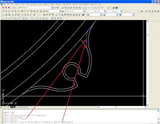
An object can be one of the cutting edges and one of the objects being trimmed. For example, in the illustrated light fixture, the circle is a cutting edge for the construction lines and is also being trimmed.
When you trim several objects, the different selection methods can help you choose the current cutting edges and objects to trim. In the following example, the cutting edges are selected using crossing selection.
The following example uses the fence selection method to select a series of objects for trimming.
You can trim objects to their nearest intersection with other objects. Instead of selecting cutting edges, you press ENTER. Then, when you select the objects to trim, AutoCAD automatically chooses the nearest objects in the drawing as cutting edges. In this example, the walls are trimmed so that they intersect smoothly.
Extend Objects
Extending operates the same way as trimming. You can extend objects so they end precisely at boundary edges defined by other objects. In this example, you extend the lines precisely to a circle, which is the boundary edge.
You can extend objects without leaving the TRIM command. Hold down SHIFT and select the objects to be extended.
Trim and Extend Wide Polylines
Wide polylines trim and extend so that the centerline intersects the boundary. Because the ends of wide polylines are right-angle corners, part of the end extends past the boundary if the boundary is not perpendicular to the extended segment.
If you trim or extend a tapered polyline segment, the width of the extended end is corrected to continue the original taper to the new endpoint. If this correction gives the segment a negative ending width, the ending width is forced to 0.
Trim or Extend in 3D
You can trim or extend an object to any other object in 3D space, regardless of whether the objects are on the same plane or parallel to the cutting or boundary edges. By using the PROJMODE and EDGEMODE system variables, you can choose one of three projections for trimming or extending: the XY plane of the current UCS, the current view plane, or true 3D, which is not a projection.
In true 3D trimming or extending, objects must intersect with the boundaries in 3D space. If the two do not intersect when you trim or extend an object in the current UCS XY plane, the trimmed or extended object might not end precisely at the boundary in 3D space. The following procedures illustrate trimming and extending using the three projection options.
(fr.autocad help)


Read More......

Thursday, June 3, 2010

Linetype

You can display and change the current properties for any object in your drawing in the following ways:
Open the Properties palette and view and change the settings for all properties of the object.
View and change the settings in the Layer control on the Layers toolbar and the Color, Linetype, Lineweight, and Plot Style controls on the Properties toolbar.
Use LIST to view information in the text window.
Use the ID command to display a coordinate location.
Use the Properties Palette
The Properties palette lists the current settings for properties of the selected object or set of objects. You can modify any property that can be changed by specifying a new value.

When more than one object is selected, the Properties palette displays only those properties common to all objects in the selection set.
When no objects are selected, the Properties palette displays only the general properties of the current layer, the name of the plot style table attached to the layer, the view properties, and information about the UCS.
You can double-click most objects to open the Properties palette when the DBLCLKEDIT command is on (the default). The exceptions are blocks and attributes, hatches, gradient fills, text, multilines, and xrefs. If you double-click any of these objects, an object-specific dialog box displays instead of the Properties palette.

Commands
DBLCLKEDIT
Controls double-click behavior
ID
Displays the coordinate of a location
LIST
Displays database information for selected objects
PROPERTIES
Controls properties of existing objects
PROPERTIESCLOSE
Closes the Properties palette
System Variables
LUPREC
Sets the number of decimal places displayed for all read-only linear units, and for all editable linear units whose precision is less than or equal to the current LUPREC value
PALETTEOPAQUE
Controls whether windows can be made transparent
PICKFIRST
Controls whether you select objects before (noun-verb selection) or after you issue a command
(fr.autocad help) Read More......